Ray Optics
In this lab, we will first observe how light refracts through a triangular prism, and use this to validate Snell's law:
$$n_1\sin(\theta_1)=n_2\sin(\theta_2)\label{snell}$$We will then study the image made by a convergent lens. In particular, we will measure the focal length using the thin lens equation:
$$\frac{1}{f}=\frac{1}{d_o}+\frac{1}{d_i}\label{thinlens}$$- 1 Laser Apparatus
- 1 Triangular Prism
- Graph Paper
- 1 Optical Bench with Lamp
- 1 Arrow
- 1 5cm Convergent Lens
- 1 5cm Divergent Lens
- 2 Lens Holders
- 1 Screen
- Record data in this Google Sheets data table
See KFJ Ch. 18 for a discussion of ray optics.
In part I, we're going to be using a triangular prism setup for which overview may be helpful.
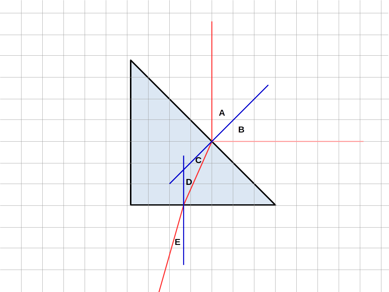
Our expectation is to observe light refracting through a prism. The following diagram will label the angles we will use:

Here, the red lines represent laser light (with the pale red being a fainter reflected ray) and the blue lines represent normals - lines constructed perpendicular to the faces of the prism.
By construction, we will take \(A\) to be \(45^\circ\). All other angles will be measured.
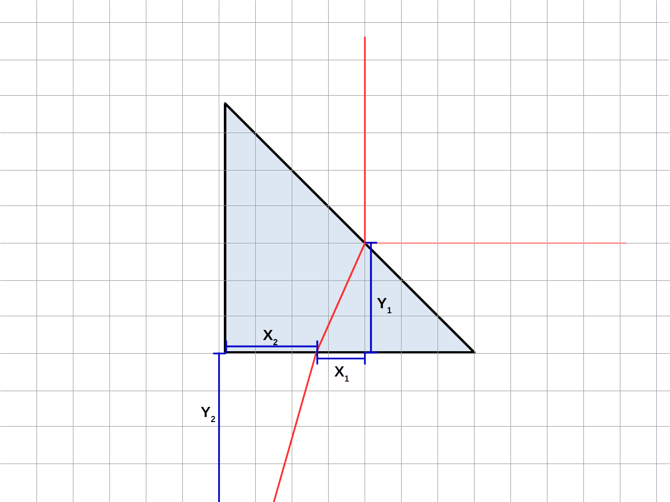
Let us label some distances we will use, as well:

Using some geometry, we can determine trigonometric relationships between our angles and our distances:
$$C=45^\circ-D$$ $$D=\tan^{-1}\left(X_1/Y_1\right)$$ $$E=\tan^{-1}\left(X_2/Y_2\right)$$Using this setup allows us to avoid measuring the angles directly, and only measure distances. (This helps to increase precision.)
Part I: Triangular Prism
Take the \(45^\circ\) triangular prism and one sheet of graph paper.
Place the triangular prism on the graph paper such that one of the shorter edges aligns with one of the lines towards the center of the page and the 45 degree angle of that side lines up with a grid line.
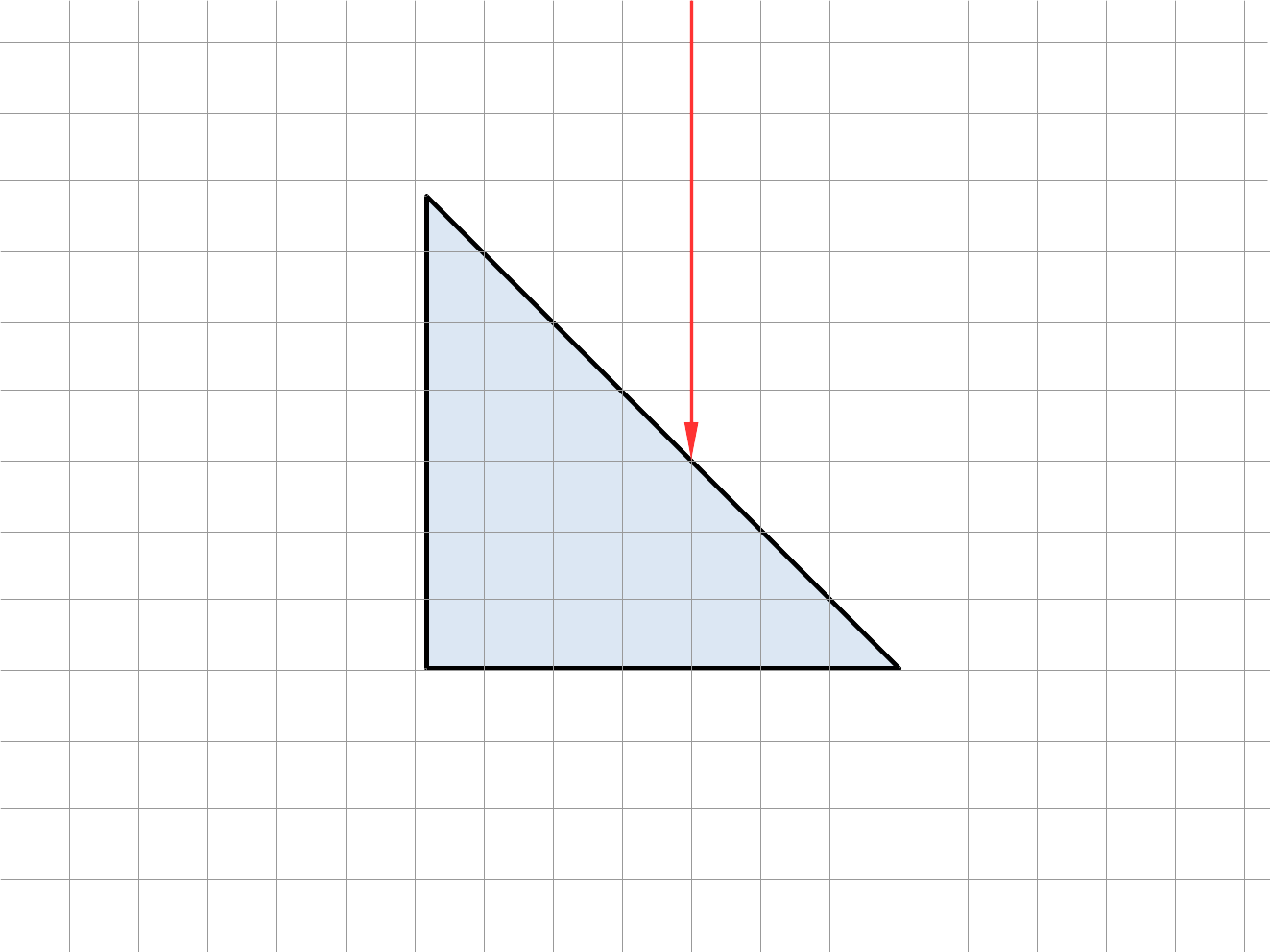
Now, take the laser and shine it on the prism perpendicularly to the edge you lined up, from the hypotenuse side. Line the laser up so that its beam travels along the gridline which has three boxes inside the prism.
Schematically, your setup should be illustrated by the following figure:

First, observe the angle \(B\) (see diagram in introduction). Note your observations, in particular the answer to question 1.
Now, measure the distances \(X_1\), \(Y_1\), \(X_2\), and \(Y_2\). Measure as precisely as you can here, ideally to sub-millimeter precision - you'll get better results that way.
Finally, we'll see total internal reflection. Shine the laser in one of the short sides such that it exits through the hypotenuse. Rotate the prism and observe where total internal reflection occurs. Note your observations, in particular the answer to questions 3-4. Tip: the intensity effects are only visible to the eye when you are almost, but not quite, at the angle of total internal reflection, so wiggle the prism right around that angle.
Part II: Thin Lenses
Begin by selecting a 5cm converging lens, and place it in the holder on the optical track. Ensure that all other components are mounted appropriately, such that the lamp shines on the arrow, then through the lens, then onto the screen.
Put the lens adjacent to the arrow, and slowly push it away until you get a focused image on the screen.
Measure the distance from the arrow to the lens holder, then from the lens holder to the screen. (You can do this by looking at the optical track.)
Now we need to slightly adjust those numbers. In fact, the lens is slightly offset from the center of the holder, by \(0.6\)cm. Take note of which direction it is offset, and add/subtract \(0.6\)cm to the two previously-calculated distances to account for this. Record these as the object distance \(d_o\) and the image distance \(d_i\), respectively.
Now, measure the vertical height both of the original arrow, \(h_o\), and of the arrow image, \(h_i\). Find some points you can measure on both the original arrow and the image (say, bottom of the arrowhead to the top) to use as a baseline, so you can have a direct and accurate comparison.
Make sure to keep track of your signs as you do these measurements; remember, a reversed image has negative height!
With that done, slide the lens closer to the screen until you find a second focal point. Repeat the measurements you did for the previous position for this new focal point.
Finally, replace the convergent lens with the divergent lens. Move the lens towards and away from the screen, and make qualitative observations. In particular, answer questions 7&8.
Part I: Triangular Prism
Using your measurements of \(X_1\), \(Y_1\), \(X_2\), and \(Y_2\), calculate angles \(B\), \(C\), and \(D\).
From those angles (and \(A=45^\circ\)), calculate the index of refraction twice: once from the angles measured at the first interface, and once from the angles measured at the second interface. You will use Snell's law, (1). Keep in mind that Excel, Google Sheets, etc. all expect angles to be inout in radians, not degrees!
Part II: Thin Lenses
For each position of the converging lens, do the following:
- Calculate the magnification as the ratio of image height to object height (with uncertainty): \(m=h_i/h_o\)
- Calculate the expected magnification as minus the ratio of image distance to object distance (with uncertainty): \(m=-d_i/d_o\)
- Calculate the focal length as measured from this position using the thin lens equation, (2)
Analysis/Observation questions:
- What do you observe about the angle \(B\) as compared with the angle \(A\)? What is this law called?
- Comment on your measurements of index of refraction. Do your values agree with each other to within uncertainty? Do they agree with the theoretical value of 1.5?
- Estimate the angle of total internal reflection. From this, calculate the index of refraction. Is this in agreement with your calculations from refraction at the interfaces?
- As you bring the prism close to the angle of total internal reflection, what happens to the angle of the refracted beam outside the prism? What happens to its intensity? What happens to the intensity of the beam inside the prism?
- Do the focal lengths you calculated from the two different positions with the lens agree with each other? What about with the theoretical value of 5cm?
- For each position, does the observed magnification (in terms of heights) match the expected magnification (in terms of distances)?
- Is there any location where the diverging lens makes an image on the screen? What does this tell you about the nature of the image (real/virtual)?
- Look at the arrow through the divergent lens (hold a sheet of paper between the light and the lens so you don't blind yourself in the process). Is the image you see magnified or demagnified, and is it upright or inverted? Do any of these properties change depending on how far from the lens your eye is?
Theoretical questions:
- For part II, take a sheet of paper and draw the ray-tracing diagram for each converging lens configuration. Set an x scale and a y scale; these can be different (e.g., horizontally 1 square = 5cm but vertically 1 square = 1cm), but be sure you are to scale in each direction.
- If we had used a 10cm converging lens instead of a 5cm converging lens in part II, would the first point at which the image focuses (as you slide away from the lamp) be closer to or farther from the lamp than it was for the 5cm lens? Why?
- If we put the arrow really far away, what would be the distance between the (5cm converging) lens and the image? What would the magnification be?
For further thought:
- In the past, in part I, we used to ask that you observe dispersion - the spread of different colors of light when they exit the prism due to different indices of refraction. (Now, we can't do that, due to using purely-red laser light instead of the white light we had then.) Based on typical dispersive behaviors, which color would you expect to be refracted the most, and which color would you expect to be refracted the least?
- In the past, we've measured the angles of refraction with a protractor. Take a typical uncertainty as \(1^\circ\) and a typical angle as \(20^\circ\). Assuming that the relative uncertainty in index of refraction is the same as the relative uncertainty in angle (which is approximately correct), and knowing the value of the index of refraction (see Q2 or your data), why might this be a problem?